


Published on Apr 02, 2024
In developing countries a large number of private vehicles used two stroke engines. A large percentage of them employ two stroke engines because of their simplicity, high power to weight ratio and low cost of maintenance. Although two stroke engines are less efficient and more polluting they may continue to popular due to low cost and maintenance.
The most serious drawback of a two stroke S.I. engine is its higher fuel consumption and higher unburned hydrocarbon emissions when compared with four stroke engine. Fresh charge loss during the scavenging process of a two stroke S.I engine is known to be the principal reason for its high specific fuel consumption and high hydrocarbon emissions. During scavenging process a part of the fresh charge mixes with the residual exhaust gas as it scavenges the cylinder while some of it is loss due to short circuiting. The net effect is that 25%-40% of the charge may be wasted resulting in high fuel consumptions. Also in two stroke engines oil is used to lubricate the engines. The excessive percentage of oil in the fresh charge increases hydrocarbon in the exhaust. It is estimated that up to 10%-15% of HC may be contributed by the lubricating oil.
Many control techniques to reduce emissions from engines may be found in the literature. The complexity and cost of the most advanced and cost of the most advanced or automatic type control system or fuel injection type do not justify their use in simpler small two stroke engines. This paper presents the field test results of technique and its concept used to improve the fuel efficiency and emissions of a two stroke engine. The estimated cost of the component is Rs.60 to Rs.90 (approximately).
In the existing engine, the air fuel mixture is induced in the crank case when the piston is at the top dead centre. From these the piston moves down, uncovers the exhaust port first and then the transfer port which contains slightly compressed charge at a pressure of about 130 kpa.This charge is transferred to the upper part of the cylinder through the transfer port. The piston is so shaped that fresh charge of fuel and air will sweep up to the top of the cylinder and push out the remaining exhaust gas through the exhaust port by means of a projection on the piston called deflector.
A small amount of unburned gases pass out through the exhaust port, when both the transfer and exhaust port are open. By the time the piston covers both these port, a small amount of unburned fuel is lost and also a small amount of burnt gas is left back in the combustion chamber. The possibility of introducing a buffer volume of air between the out going and incoming charges has frequently been advocated. Historically attempts have been made to minimize the short circuit losses of fuel ever since two stroke engines were introduced. In recent attempts made at the Indian Institute of Technology, Madrrass and the Indian Institute of Petroleum, air act as a buffer gas to separate the fresh charge and the burned gas. Such a volume of substantially fixed value may be expected to reduce both liability to mixing and transfer of heat between the fresh charge and the burned gas.
A pair of reed valves was employed to introduce the air from out side to the top of transfer passages that would remain between the crank case content of live mixture and the closed transfer port to the cylinder. When the later opened, air would be pumped in a head of mixture forming a buffer screen of air between the burned gas and the fresh charge
The reed valve is a unidirectional valve which allows flow in one direction only. It does not allow the flow in the opposite direction. The fluid enters through the opening provided at the flange end of the valve. The flange is provided with holes for admitting a nut so that the valve can be fitted to the valve casing. The openings are covered by a blade on the outer surface. Each blade is fitted to the valve body at one end by a pair of rivets, so that the rivets lie parallel to the flange surface. The blade is made up of tempered material so that it is flexible when fluid pressure acts on it.
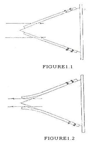
The blades stick to the valve so that the holes below it reclosed. This occurs when the fluid tries to flow in the direction of arrows as shown in fig.1.1. When the fluid tries to flow as shown in fig.1.2 one end of the blades move away from the valve body so that the opening below it are exposed and the fluid flow in the direction shown by arrows. The position of the valve is open. Hence it is seen that valve allows fluid only in one direction.
The reed valve is fitted at the transfer port of the engine cylinder. The valve is fitted by making drilled hole on the walls of the transfer port of the
cylinder. The position of the bore is located such that minimum air resistance is increased. The bore is threaded internally.
The reed valve is enclosed in a casing. The casing, reed valve, and the inlet flange to the reed valve are boiled and held together. The casing has a connecter and is threaded externally. The connecter is fixed to the engine cylinder so that the external thread of the connecter and the internal thread of the engine cylinder fit. The prime purpose of fitting the reed valve at the inlet of the engine cylinder is to reduce the loss of unburnt charge during scavenging so that the efficiency of the system can be increased by admitting the fresh air instead of fuel air mixture for scavenging.
In the improved design two reed valves are fitted at the upper end of transfer duct connecting the crank case and the cylinder as shown in fig.2. The reed valves are positioned in such a way that air would enter in a direction perpendicular to the cylinder axis and along its radius. Air from atmosphere enters the crank case in two different directions,(1) through the carburetor ,along with the fuel in the conventional way and (2) through the two reed valves fitted at the transfer ports on each side of the engines. When the piston moves upward, the pressure inside the crank case is lowered to the sub atmospheric.
This causes the air from the atmosphere to flow into the transfer passages through the reed valves and the fresh charge enters the crank case in the normal way through the inlet passage. During the down ward stroke of the piston, the pressure in the crank case closes the reed valves. When the piston descends further transfer ports open and air in the transfer passage enters the cylinder ahead of the fresh charge. The air pushes the exhaust gases out and acts as a buffer screen between the two mediums, the charge and burnt gas. Air becomes the main component that is lost to the atmosphere through the exhaust port.The charge that follows it is retained in the cylinder to a greater extend
Experiments were carried out on a small capacity (55cc displacement volume, developing 1.7kw at 5000 rpm) crankcase compression, loop scavenged, two stroke S.I engine. This type of engine is used in light two wheelers in India. The engine was coupled to eddy current dynamometer for torque and speed measurement. An infrared gas analyzer was employed to measure HC and CO emissions level in the exhaust cylinder. Two reed valves are fitted at the upper ends of the transfer ducts connecting the crankcase and cylinder.Polythene tube and a T-joint were used to inter connect the air flowing through the two reed valves and make a common connection.
A standard needle lift valve (4.8mm diameter, total area of about 18.1 mm square) was employed to control air flow through the common connection. Variable load tests were conducted at constant engine speeds of 3000 rpm and 4500 rpm.Performance and emissions were studied with various amounts of air flow through the reed valves by changing the opening area of control valve. Positions IA, IB and IC represent the area of opening in the control valve of about 0.8 mm square, 1.16 mm square and 2.41 mm square respectively. In a two wheeled moped or scooter continuous adjustment of control valve during running condition is difficult and hence an optimum area of opening of the control valve was found and experiments were carried out with this opening area for entire range of engine operation.
| Are you interested in this topic.Then mail to us immediately to get the full report.
email :- contactv2@gmail.com |
